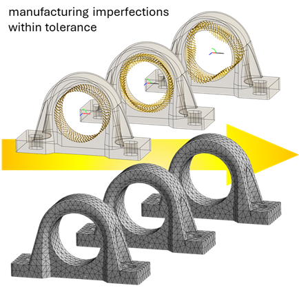
{svg/flag_W.svg} Tolerance Challenges

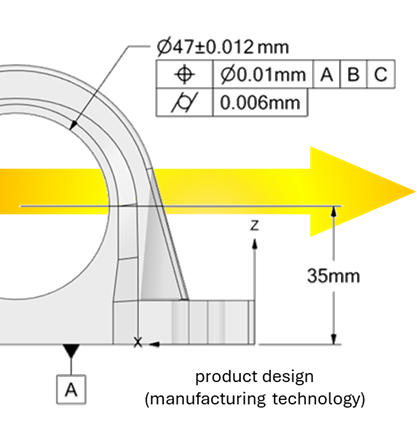
- Reduction in manufacturing costs by selecting an appropriate production technology for the required tolerance.
- Increase in the reliability of products that are sensitive to geometric tolerances.
- Reduction in the number of prototypes through the proper selection of geometrical tolerances.
- Improvement of simulation accuracy by considering operational loads during the evaluation of geometric tolerances.
- Bringing GD&T (Geometric Dimensioning and Tolerancing) tools directly into your FEA simulation
?"Do operational deformations, such as loss of cylindricity or flatness, affect the reliability of your products? And how do you solve this?"
{svg/key_B.svg} Solution for FEA
With GDT4FEM, you can both apply geometrical imperfection within tolerance bands and evaluate ISO or ASME requirements, including the influence of operational deformations directly within your FEA workflow.
[GDT4FEM] Inside Ansys
- Fully integrated into Ansys Mechanical.
- GD&T imperfection and assessment.
- Assess tolerance compliance under operational loading conditions
[GDT4FEM] Online
- Free online web-app
- GD&T (STL based, universal) assessment.

[GDT4FEM] inside Ansys
GDT4FEM inside Ansys is a plugin for Ansys Mechanical that brings tolerance-aware simulation directly into your FEA workflow.
The tool is designed to:
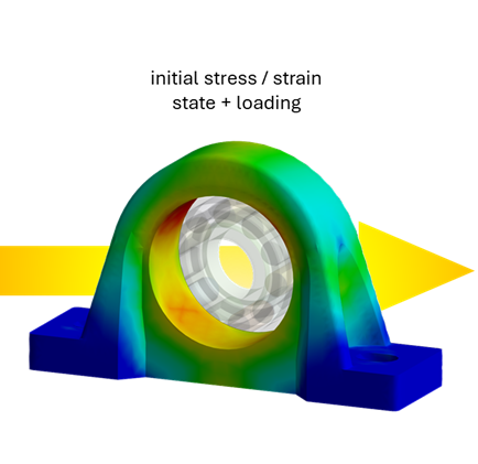
- Include [Geometrical Imperfection] within defined tolerance limits during the preprocessing stage (to include Initial Stress/Strain State and geometrical shape into your simulation).
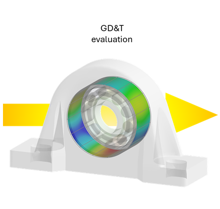
- Evaluate [GD&T] features after applying operational deformations in the postprocessing stage.
GDT4FEM inside Ansys gives you a complete workflow to simulate, visualize, and optimize the impact of geometric tolerances on product reliability.
The look-and-feel user interface contains integrated help for easy orientation in GD&T setup.
?"Do you know how much material could be saved without compromising reliability below an acceptable limit, specifically considering relative deformations during operation?"
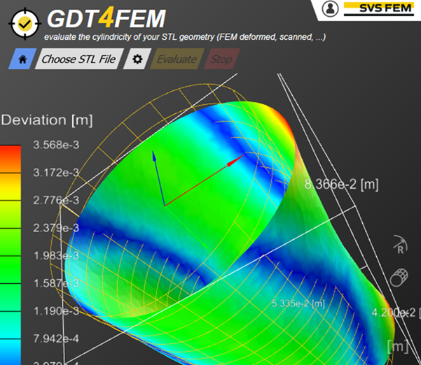
[GDT4FEM] Online
GDT4FEM Online is a browser-based tool for fast and flexible [GD&T] evaluation. It works independently of any FEA software and supports a range of [Geometrical Tolerance] .
The tool is designed to:
- Evaluate features like [Cylindricity], [Flatness], [Straightness], and more.
- Visualize deviations directly on the deformed 3D geometry in a browser.
Whether you're validating simulation results or inspecting scanned parts, GDT4FEM Online makes tolerance analysis simple, visual, and accessible.
Use the free version for quick cylindricity checks.
{svg/bearing_W.svg} Use Cases
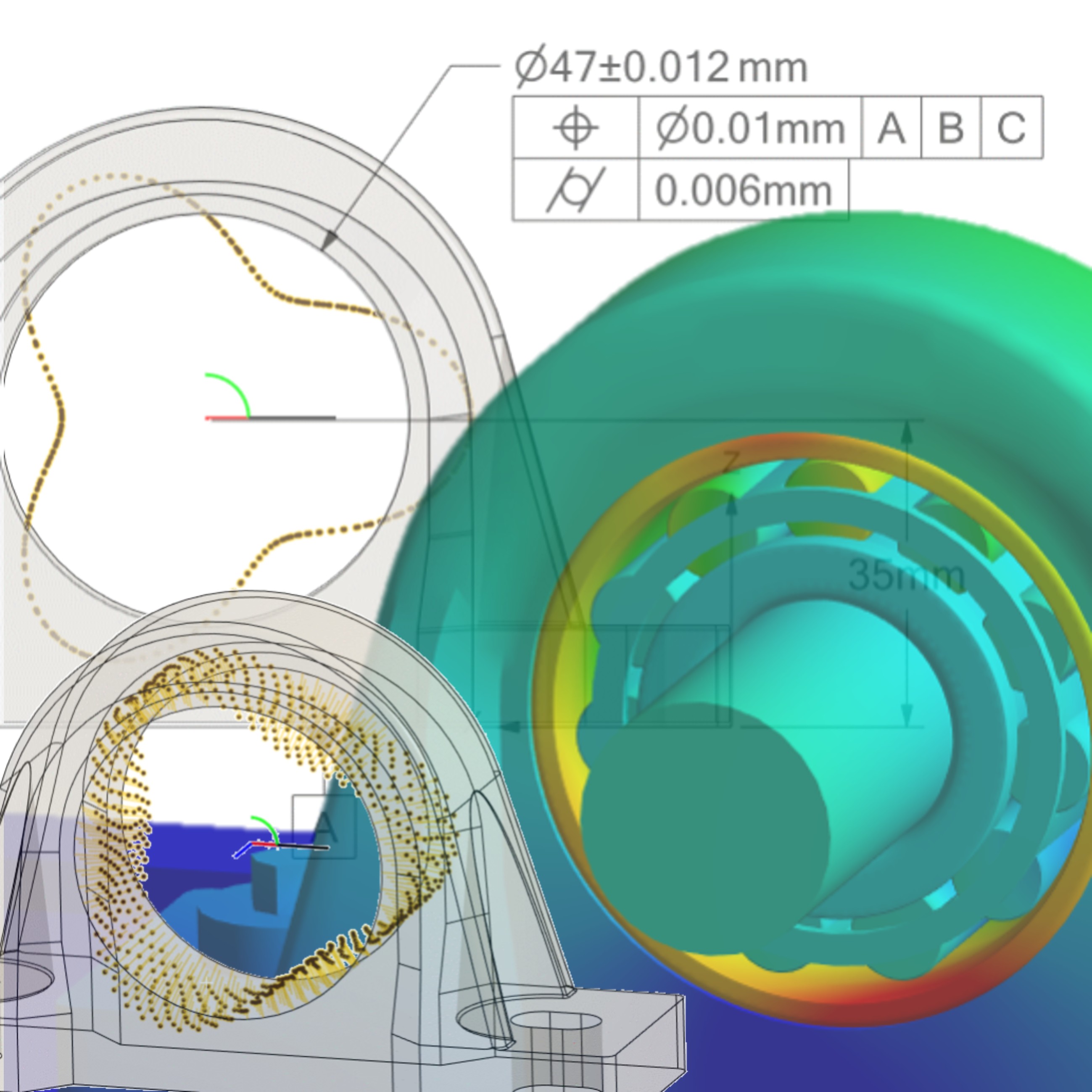
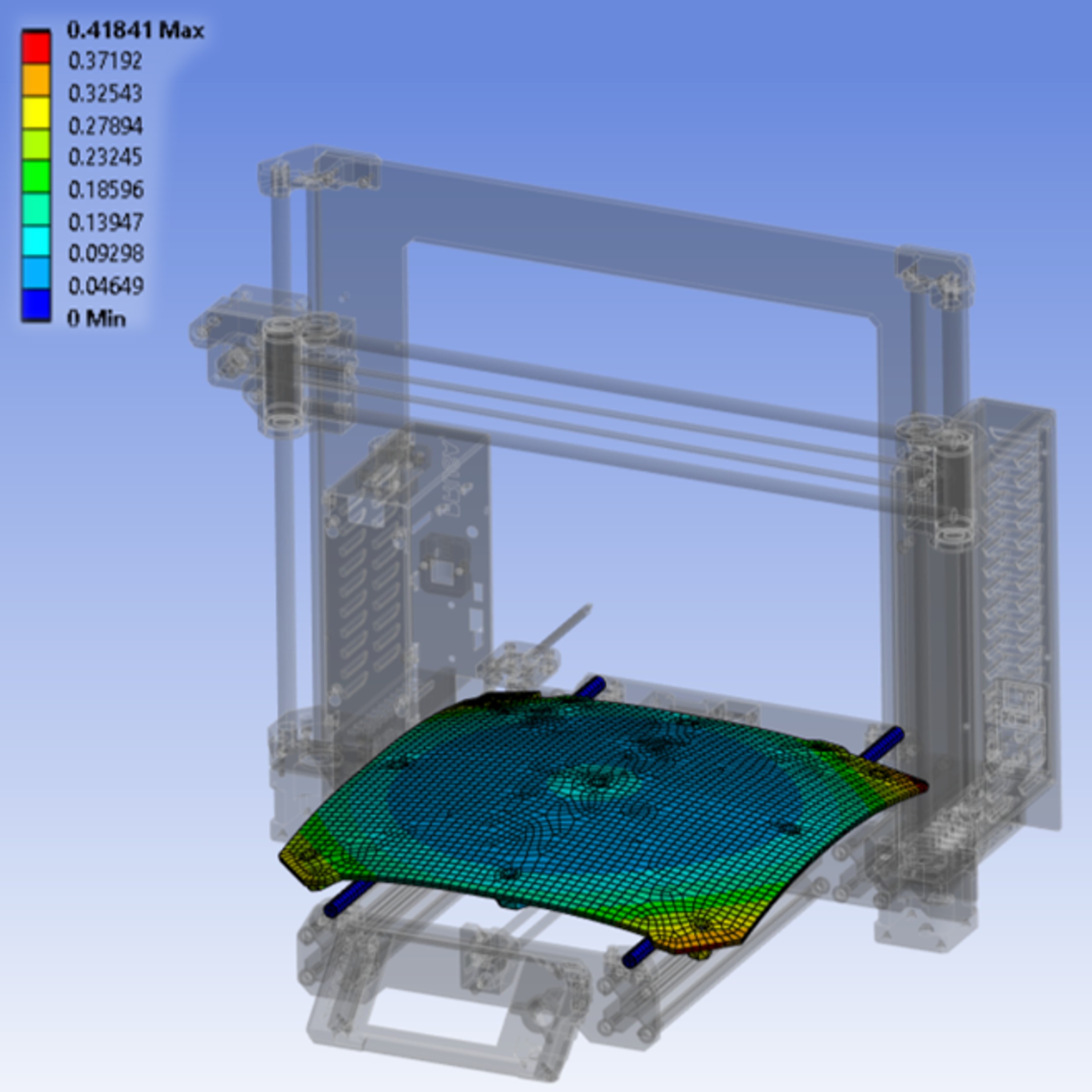
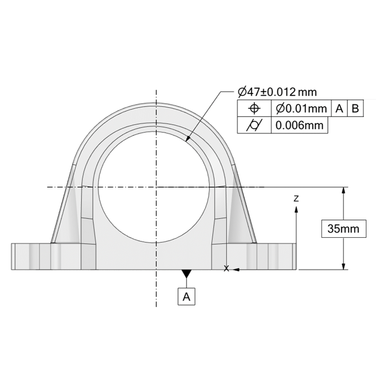
Housing Initial State
Initial assembly state due to cylindricity imperfection in Ansys
Issue:
During prototyping, the assembly showed excessive vibrations due to
manufacturing imperfections in the bearing housing, even within
specified tolerances.
Solution with GDT4FEM:
Model of geometrical imperfection (cylindricity) were included in the design analysis,
enabling shape optimization and proper
selection of cylindricity tolerance.
Benefit:
Reduced prototype iterations and manufacturing costs
through optimal tolerance definition already in the design phase.
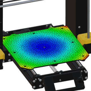
Heat Bed Warping
Heat bed warping in 3D printing due to thermal load (Flatness evaluation in Ansys)
Issue:
Uneven heating of the 3D printer’s bed,
combined with support structures, caused
warping during printing. This led to poor
layer adhesion and print failures.
Solution with GDT4FEM:
Flatness evaluation was used to analyse the deviation
field of the heat bed in every printing stage.
By simulating thermal
effects and geometrical imperfection,
the bed design was optimized
to minimize warping.
Benefit:
Reduction of the bed warping
improved print quality of the 3D printer.
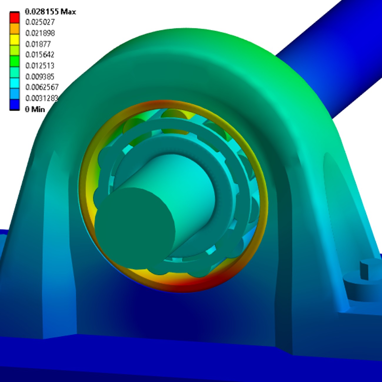
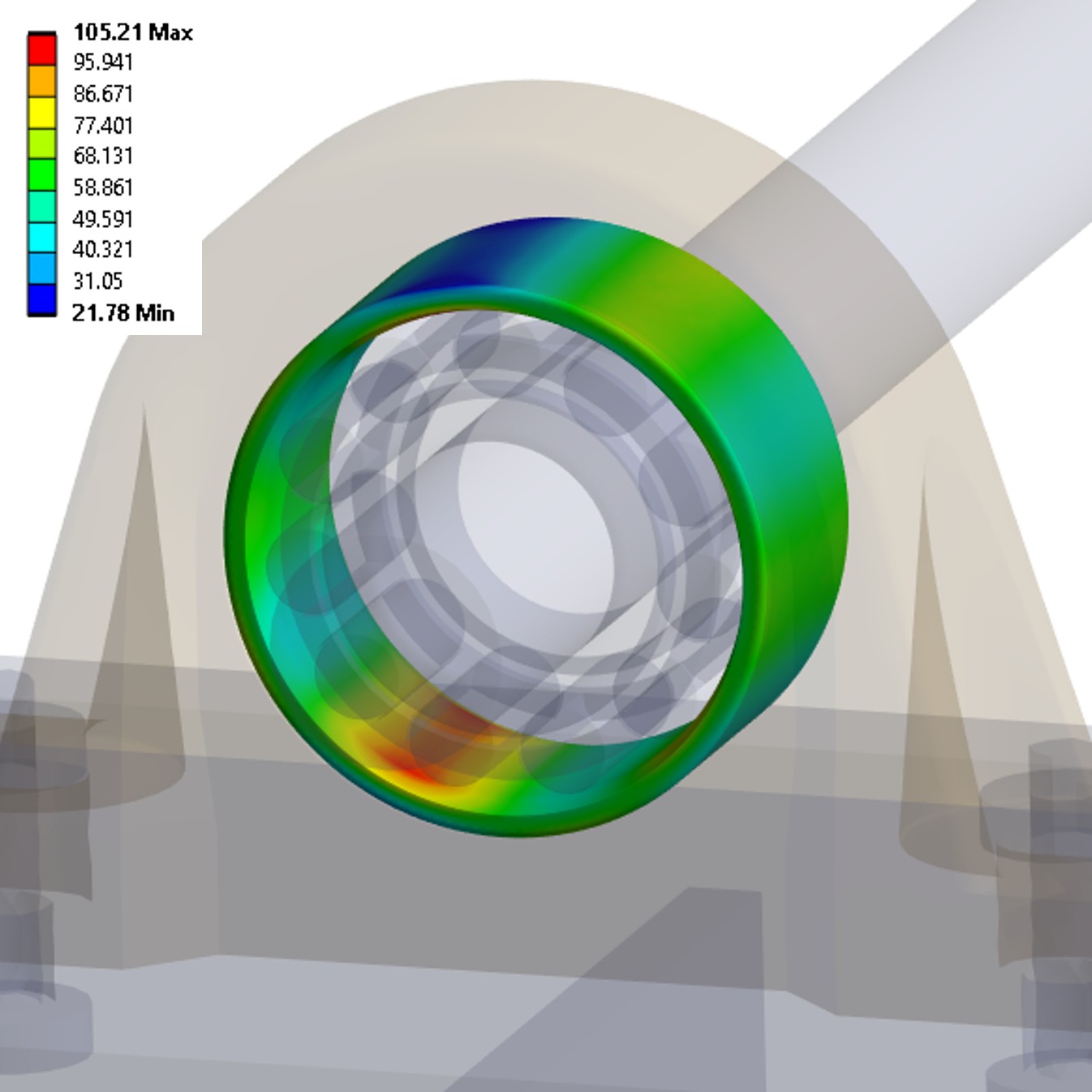
Bearing Reliability
Cylindricity evaluation in ANSYS
Issue:
Excessive bearing wear and increased friction were observed
due to misalignment between bearing seats across
the gearbox assembly.
The concentricity error accumulated from multiple components within tolerance.
Solution with GDT4FEM:
Assembly-level geometrical imperfection were simulated already during design,
allowing identification of critical misalignment and
optimization of concentricity and cylindricity tolerances.
This led to a decrease in bearing load during operation.
Benefit:
Improved bearing life and reduced maintenance costs
while avoiding unnecessarily tight machining tolerances.
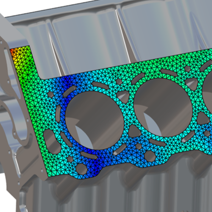
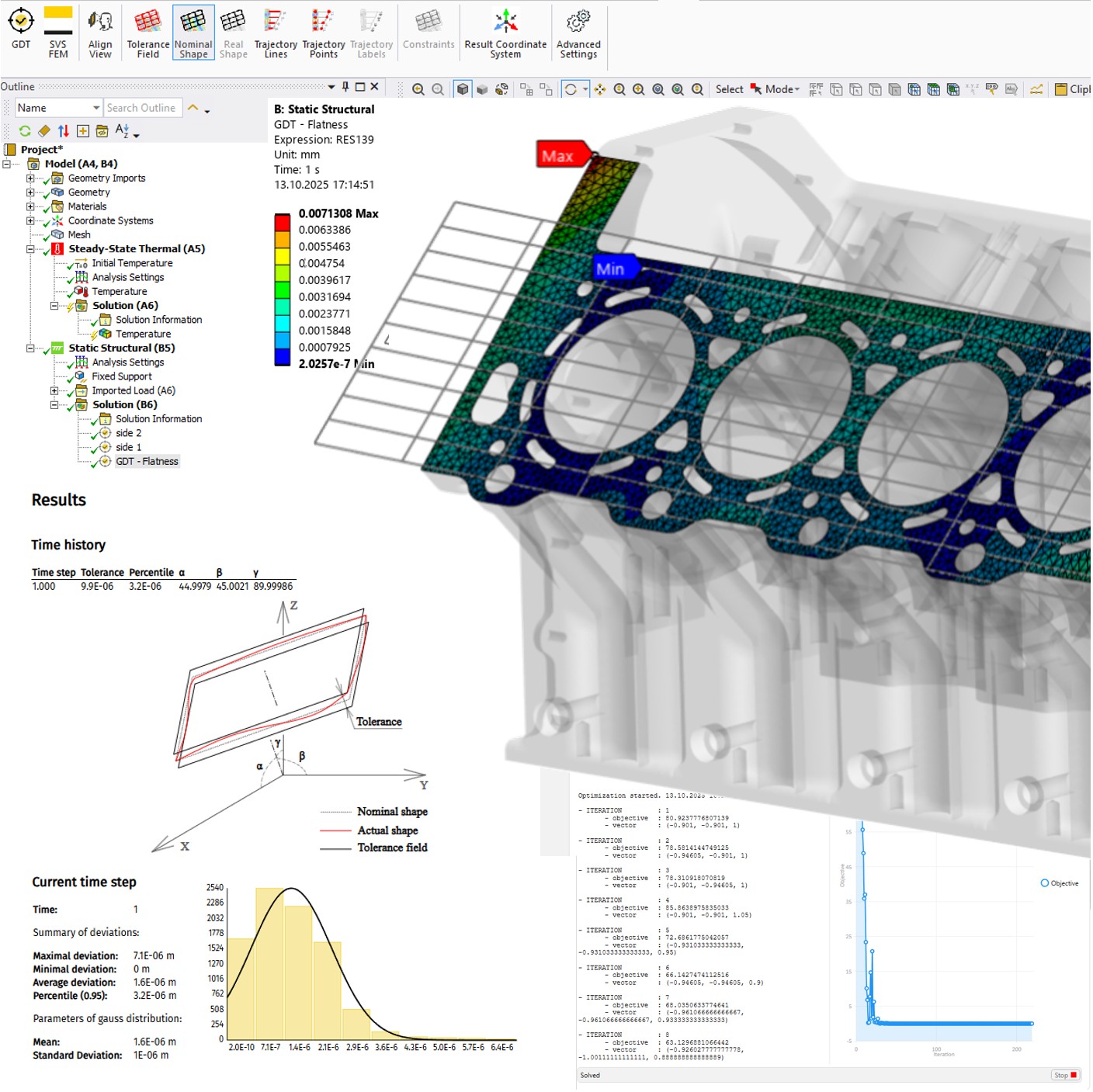
Engine Block Contact
Flatness evaluation in Ansys
Issue:
During testing, a newly developed combustion engine exhibited leakage issues
caused by uneven thermal expansion between the engine block and the cylinder head.
Solution with GDT4FEM:
Using the flatness assessment simulation, deviation of contact
surfaces under real operating temperatures and loads were evaluated.
These insights enabled to redesign the parts and eliminate the leakage issue.
Benefit:
The design flaw was identified and resolved early in the development phase,
preventing costly failures
had the defective design reached serial production.
?"Do you consider initial stresses caused by Geometrical Imperfection, even those acceptable within the required tolerances, in your calculations? Are the initial stresses negligible?"
{svg/capa_B.svg} Capabilities
Content
- Imperfection
- Assessment
- Cylindricity
- Flatness
- Straightness
- Curvature
- Constraints
- Distance (body-to-body)
- Compare (body-to-body)
If you're missing a specific feature, check our Roadmap or Contact us. We’re continuously expanding based on user needs.
Standards such as ISO 1101 and ASME Y14.5 primarily define manufacturing accuracy. But we go further: with the GDT4FEM tool you can incorporate into FEM analysis:
- the initial shape (including imperfection, in compliance with tolerances)
- operating conditions (loads)
This enables highly accurate prediction of product reliability.
For example, in the case of cylindricity, GDT4FEM is able to introduce a model of the initial shape as well as perform a best-fit of the ideal cylinder to the finally deformed geometry from FEM analysis, in order to assess cylindricity according to the standard.
Imperfection
[Geometrical Imperfection] refer to deviations in material geometry from ideal shape caused by manufacturing process (e.g. casting, assembling, ...)
Inclusion of geometric Imperfection in structural calculations (FEM) may be necessary for several analyses:
- buckling analysis (nonlinear)
- to evaluate/include initial stress/state
- [GD&T] assessment under operational loads
An approach to quickly and easily include geometric Imperfection in a FEM model is using morphing in GDT4FEM (see [Mesh Morphing]).

Assessment
The geometrical tolerancing assessment functions in GDT4FEM provide simulation engineers with valuable insights into operational deformations that are often difficult, costly, or even impossible to measure experimentally. Complex questions like: “Does the bearing outer ring inside an engine still meet its cylindricity tolerance even under operational loads?” can now be answered with confidence!
By combining [Mesh Morphing] with geometrical tolerancing assessment (both integrated in GDT4FEM) engineers can evaluate the impact of [Geometrical Imperfection] and the operational deformations early in the design process and thus correctly predict strength and reliability of the part.

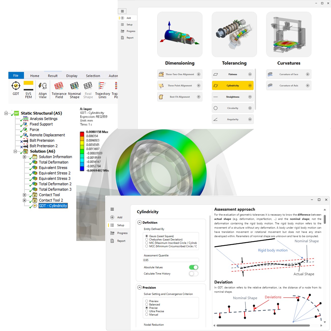
Cylindricity
Cylindricity is a 3-Dimensional tolerance that controls the overall form of a cylindrical feature. The analyzed cylindrical feature must be enclosed between two concentric cylinders.
There are four procedures available for finding the nominal shape regarding cylindricity in [Assessment] module:
- Best-fit (Gauss, Chebyshev)
- Maximal Inscribed Cylinder (MIC)
- Minimum Circumscribed Cylinder (MCC)
See Gauss, Chebyshev, MIC, MCC for more about solvers.
There is posibility to apply 'N-lobed Rosette Curve' shape model of any cylinderical surface in [Imperfection] module.

Flatness
Flatness describes the deviation of a plane surface from the theoretical plane. The analyzed planar feature must be enclosed between two parallel planes.
There are two procedures available for finding the nominal shape regarding Flatness in [Assessment] module:
- Best-fit (Gauss, Chebyshev)
See Gauss, Chebyshev, MIC, MCC for more about solvers.
There is posibility to apply deflected shape model of any surface in [Imperfection] module.

Straightness
Straightness is a tolerance that controls the form of an axis to ensure it is straight enough along its length.
There are two procedures available for finding the nominal shape regarding Straightness in [Assessment] module:
- Best-fit (Gauss, Chebyshev)
See Gauss, Chebyshev, MIC, MCC for more about solvers.
There is posibility to apply deflected shape model of any cylindrical surface in [Imperfection] module.

Curvature
Surface curvatures are important to know for several purposes:
- shape analysis
- corresponds to bending moments
It is important to remember that curvature is the second derivation in some direction of some coordinate.
GDT4FEM includes tools for plotting curvature, both contour plot and diagram plot.


Constraints
GDT4FEM implements several types of constraints:
- Radius
- Orientation (axis, normal)
- Location (point on axis)
All constraints can be defined as:
- Range - vector/value can be optimized but result of optimization must be within specified tolerance to constraint.
- Exact - constraint is exact and vector/value cannot be changed.
For example, bearing has to be oriented within given range in steering column axis, or mounting surface of specimen has to be orientied exactly to normal of hydraulic press jaw

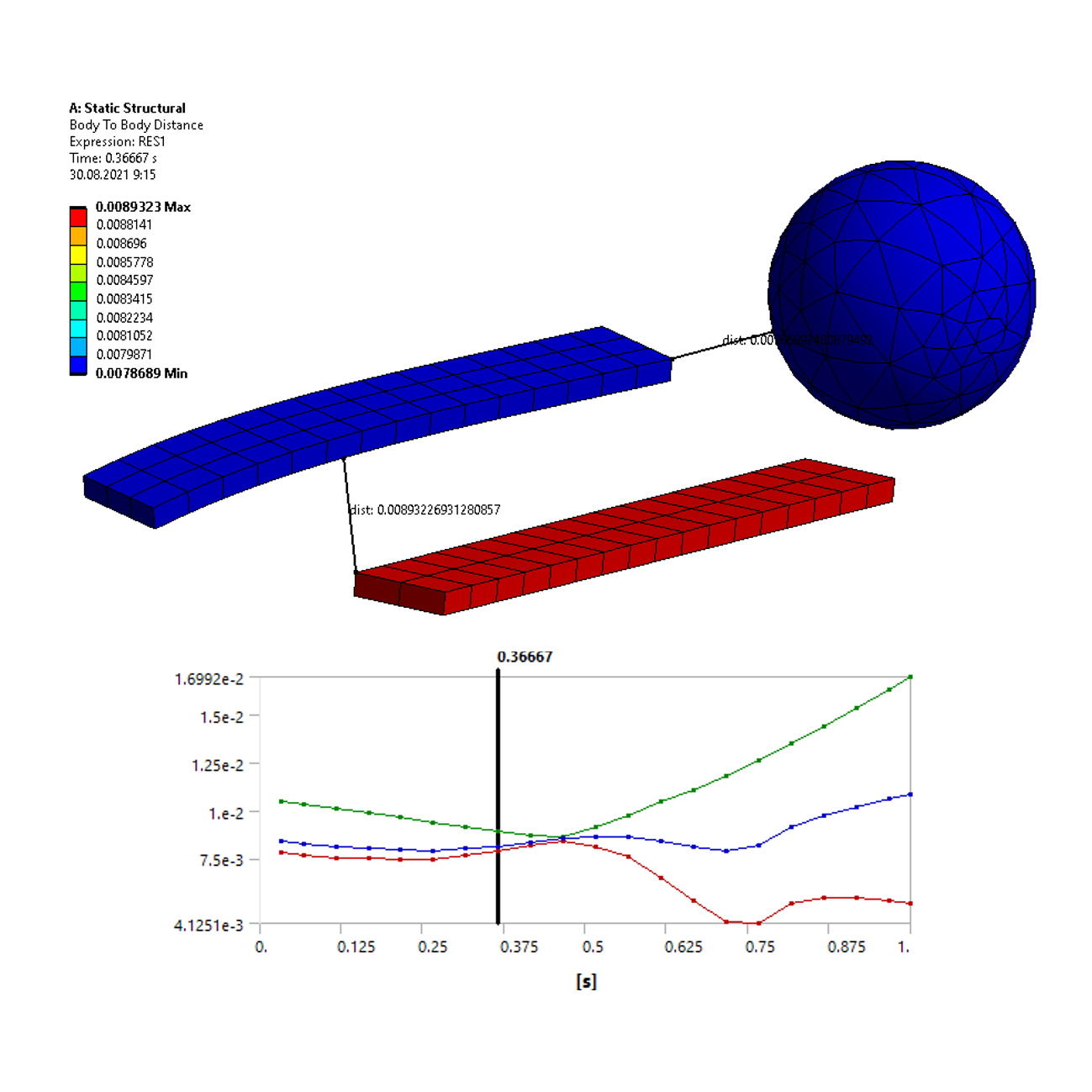
Distance (body-to-body)
In GDT4FEM, the distance function calculates the nodal distance between all selected bodies over the entire solution time history and then determines their minimal distance in 3D space.
This is, for example, important for analyzing vane opening in a turbocharger or the actual valve lift.

Compare (body-to-body)
In GDT4FEM, the compare function calculates the nodal deviations of a part before and after deformation, while excluding any [Rigid Body Motion]. This ensures that only the true deformation effects are measured, making it ideal for comparing differences between the undeformed and deformed shapes.
Three evaluation methods are available:
- Best-fit (Gauss, Chebyshev)
- 3 Points
- Datums alignment (3-2-1)
This general evaluation case makes it possible to assess position or dimensions in accordance to [GD&T], or to solve general [Deviation] as a part of [Relative Deformation] problems.

Roadmap
GDT4FEM is built upon a solid foundation of research, development, and practical application. Drawing from this experience, the tool has evolved into a robust framework for addressing engineering challenges dealing with reliability of products.
At the same time, its architecture and methodology provide a forward-looking basis for further advancements, ensuring that GDT4FEM will continue to play a key role in the future development of engineering analysis and design.

{svg/theory_W.svg} Theory
Content
GDT4FEM tools are built on a solid foundation of mechanical and mathmatics theory but it’s designed to be practical and intuitive.
You don’t need to dive deep into the math just know that the engine powering GDT4FEM delivers accurate, actionable insights from real geometry.
GDT4FEM can be divided into two theoretical areas:
- [Geometrical Imperfection] - modification of the mesh shape to better reflect reality through morphing within the range of [GD&T] tolerances
- [Tolerance Assessment] - evaluation of [GD&T] tolerances on a deformed mesh, considering both operational deformations and initial imperfections
GD&T
(Geometric Dimensioning and Tolerancing)
It is a system for accurately and unambiguously defining geometric requirements for parts and assemblies. It is used in technical drawings and 3D models to specify form, orientation, location, and size tolerances.
Its main goal is to ensure part interchangeability, reduce manufacturing costs, and improve communication between design, production, and inspection. GD&T defines the permissible geometrical [Deviation] relative to reference features (datums). The system is standardized primarily by ISO 1101 (international standard) and ASME Y14.5 (American standard).

Geometrical Imperfection
Various mathematical models of actual imperfections can be applied. Typically, smooth functions such as sine, cosine, or polynomials are used. For example, by applying a sine function dependent on the angle to vary the radius, one can create an imperfection model that realistically appears when scanning real holes.
For applying geometrical imperfection in FEM calculations, the most effective approach is to shift the nodes ([Mesh Morphing]).

Initial Stress/Strain State
The initial stress/strain state refers to internal stresses and strains present in a structure after has been assembled. These arise from dimensional differences and interactions between assembled parts, for example:
- bearing is mounted on a shaft
- flange bolts are pretending
Such stresses and strains may occur even when components meet prescribed geometrical and dimensional tolerances. Their influence should therefore be considered in structural assessment to ensure accurate evaluation of strength and reliability.
Neglecting initial stress/strain can lead to non-conservative structural assessment.
[Mesh Morphing] can be an effective way to easily modify the initial geometry in an FEM calculation and investigate the initial state.

Mesh Morphing
Mesh morphing is the process of deforming a computational mesh (FEM) to match the actual geometry of a structure including [Geometrical Imperfection], while preserving the connectivity and quality of the elements.
Three cloud of nodes:
- Force-morphed - nodes are moved to new location by specified function
- Free-morphed - nodes are moved to average location by neighbours
- Fixed - nodes stay at orginal location

Buckling Analysis
Buckling is sudden lateral deflection of a structural member subjected to compressive stress, occurring at or above a critical load. Buckling analyses are commonly performed in engineering practice in two variants:
- Linear Buckling Analysis (eigenvalue buckling) provides a quick estimate of the critical load factor and corresponding buckling mode shapes. It assumes perfect geometry and elastic material behavior, making it suitable for preliminary design.
- Nonlinear Buckling Analysis accounts for [Geometrical Imperfection], material nonlinearity, and large deformations. It provides a more accurate prediction of buckling loads and post-buckling behavior, essential for final design verification.

Tolerance Assessment
The core functionality of GDT4FEM is the removal of [Rigid Body Motion] (translations and rotations) from the computed displacements.
This makes it possible to evaluate the [Relative Deformation] of a structure (the true change in shape) by comparing the actual geometry shape under load with the nominal, undeformed geometry.
Thanks to this, you can focus on the important deviations that affect performance, independent of overall movement in space.
actual shape = default shape + rigid body motion + relative deformation

Geometrical Tolerance
It determines the limit shape/dimension of the designed geometry that is acceptable in according to a standard or regulation (see [GD&T]).
The actual shape of the geometry (measurement, calculation, etc.) is compared with the limit shape/dimension.
This is crucial for assessing the reliability of the structural design concerning serviceability limit states.
Rigid Body Motion
Rigid body motion is the movement of a body in space without any change in its shape or size.
In this case, no relative deformation occurs (the distances between nodes remain constant) and only translations and rotations are observed. (Relative Deformation).

Relative Deformation
It is the difference (vector) between the current deformed shape and the nominal (original) shape, which is aligned to the actual position, including rotation.
The translating and rotating of original shape is generally callled as Rigid Body Motion.
Can be devided to components (e.g. [Deviation]).

Deviation
It is a component of [Relative Deformation] and it is main quantity for GDT4FEM assessments.
For example, normal direction to nominal shape is used for deviation evaluation if [Cylindricity] or [Flatness] type is assumed. Overall relative deformation is used in case of Compare (body-to-body) assessment.
The deviation is evaluated by solvers using numerical methods.

Gauss, Chebyshev, MIC, MCC
According to ISO 1101, there are four standard methods for computing the nominal (reference) shape of a feature, often used in tolerance analysis:
- Gauss Method - the nominal shape is determined by minimizing the sum of the squares of deviations of all nodes.
- Chebyshev Method - the nominal shape is determined by minimizing the maximum deviation among the nodes.
- Maximum Inscribed Element - the nominal shape is computed as the largest feature that fits entirely inside the measured geometry.
- Minimum Circumscribed Element - the nominal shape is computed as the smallest feature that fully encloses the measured geometry.

Constraints and Solvers
Constraints limit the design space of the searched geometry entity. For example, the orientation vector of a cylinder axis can either be fixed explicitly or restricted to lie within a specified tolerance range.
The introduction of such constraints transforms the determination of the nominal shape into a non-linear optimization problem. To solve this effectively, suitable numerical solvers must be employed, using algorithms such as evolutionary methods or gradient-based approaches.
{svg/tick_B.svg} References
Danfoss
Danfoss is a global leader in engineering solutions, specializing in refrigeration, air conditioning, heating, motor control, and mobile machinery.
Danfoss uses GDT4FEM to evaluate and optimize critical components, ensuring that even minor deviations in geometry are identified and addressed early in the design and manufacturing process.

{svg/contact_W.svg} Contact
[GDT4FEM]

www.svsfem.cz
SVS FEM s.r.o.
Trnkova 3104/117c
628 00 Brno, Česká republika

Ing. Zdeněk Čada, Ph.D.
+420 543 254 554
zcada@svsfem.cz